
Scope:
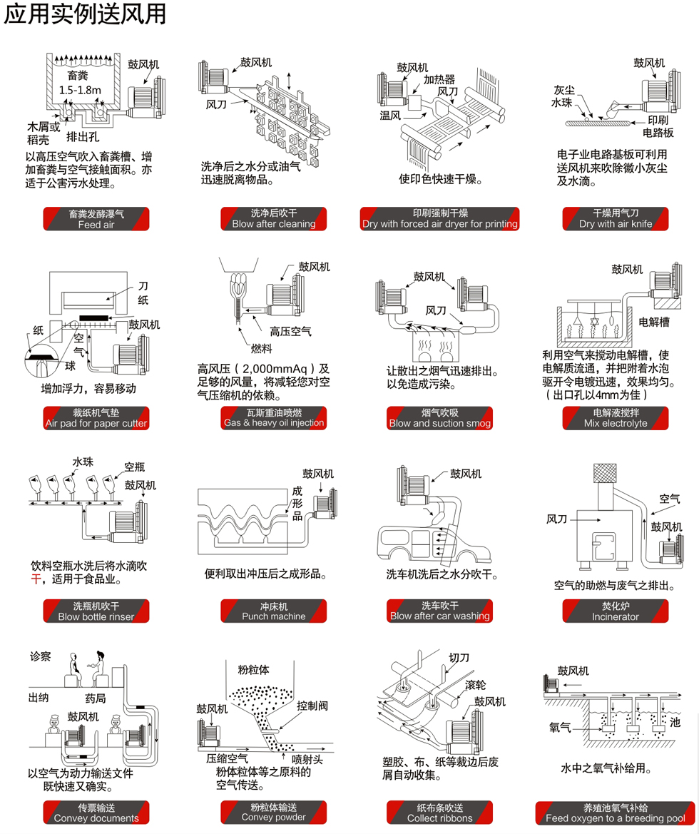
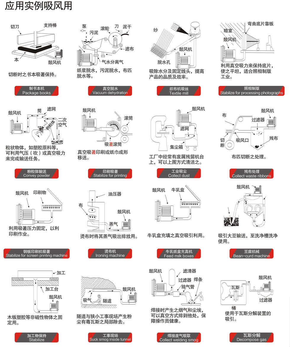
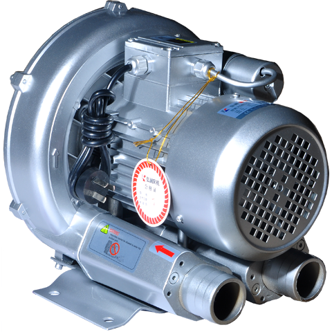
Pneumatic transport systems, vacuum lifting and clamping systems, packaging machines, bagging / bottling / filling systems, soil improvement, foam forming systems, mail classification and parcels, food processing systems, laser printers, dental vacuum suction machines, paper processing systems, two-stage fans, printers, duplicating machines can meet higher requirements, darn machines, fishpond ventilation systems, gas analysis, swimming pool ventilation。
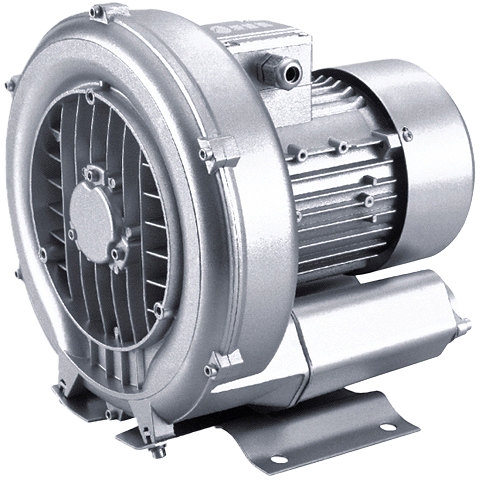
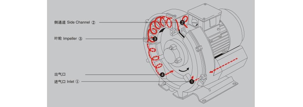
Principle:
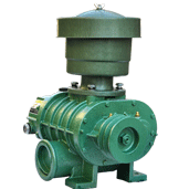
When the impeller of the high-pressure blower rotates, due to the centrifugal force, the wind vane makes the gas move forward and outward, thus forming a series of spiral movements. The air between the blades of the impeller is spirally accelerated and the gas outside the pump body is squeezed into the side groove (inhaled by the suction port T). When it enters the side channel ②, the gas is compressed, and then it returns to the blades of the impeller 1 to accelerate the rotation again. When the air passes through the impeller and side slot along a clamped spiral track, each impeller increases the degree of compression and acceleration. With the progress of rotation, the function of the gas increases, which further increases the gas pressure along the side channel. When the air reaches the connection point between the side seeding and the discharge flange (the side channel narrows at the outlet & gt;), the air is extruded out of the blade and discharged from the pump body through the outlet muffler 4.
| Model | Motor | Weight | Noise | Qmax | Vacuum | Mpa | Vacuumvalves | |||
| Rate | Rated | |||||||||
| Output power | Voltage | Electricity | Type*Model | |||||||
| Hz | KW | V | A | KG | Db(A) | m³/h | mbar | mbar | 2B*4... | |
| XGB4-10 | 50 | 0.75 | 220/380 | 4.8 | 14 | 56 | 145 | -130 | 130 | 1*2B*2110/...2141 |
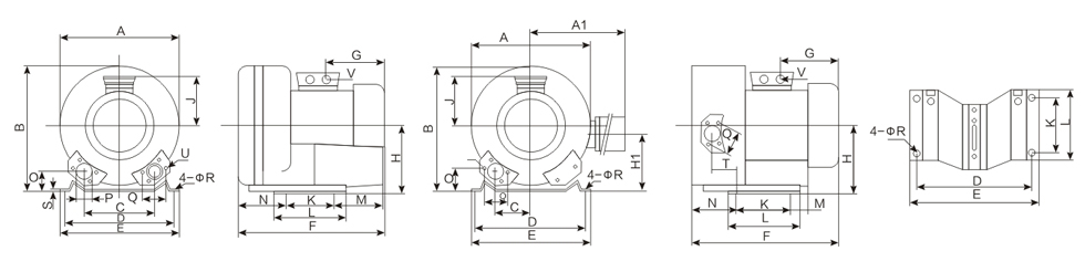
Drawing
| Model | XGB1-10A | XGB1-10B | XGB2-10 | XGB2-20 | XGB3-10 | XGB4-10 | XGB4-20 | XGB5-10 | XGB5-20 | XGB6-10 | XGB7-10 | XGB7-20 | XGB8-10 | XGB8-20 | XGB9-10 | XGB9-20 |
| Phase | 1 | 1 | 3 | 3 | 3 | 1 | 3 | 1 | 3 | 3 | 3 | 3 | 3 | 3 | 3 | 3 |
| A | 184 | 200 | 246 | 284 | 268 | 286 | 322 | 334 | 372 | 360 | 382 | 426 | 451 | 500 | 550 | 615 |
| A1 | - | - | - | 316 | - | - | 324 | - | 411 | - | - | 426 | - | 549 | - | 780 |
| B | 200 | 212 | 247 | 270 | 272 | 302 | 315 | 337 | 371 | 366 | 384 | 410 | 461 | 490 | 569 | 607 |
| C | 80 | 86 | 90 | 45 | 93 | 115 | 58 | 120 | 60 | 122 | 125 | 63 | 152 | 152 | 207 | 103.5 |
| D | 157 | 184 | 205 | 205 | 205 | 225 | 225 | 270 | 270 | 284 | 290 | 290 | 356 | 356 | 360 | 360 |
| E | 172 | 204 | 230 | 230 | 230 | 255 | 255 | 320 | 320 | 325 | 325 | 325 | 394 | 394 | 415 | 415 |
| F | 205 | 227 | 219 | 316 | 260 | 294 | 401 | 314 | 465 | 354 | 377 | 473 | 450 | 589 | 525 | 752 |
| G | 82 | 105 | 92 | 135 | 92 | 160 | 191 | 160 | 190 | 191 | 191 | 191 | 230 | 230 | 268 | 345 |
| H | 93 | 110 | 128 | 128 | 141 | 154 | 154 | 175 | 175 | 192 | 197 | 197 | 240 | 240 | 300 | 300 |
| H1 | - | - | - | 106 | - | - | 153 | - | 144 | - | - | 162 | - | 199 | - | 234 |
| J | 72 | 98 | 101 | 111 | 101 | 120 | 128 | 120 | 135 | 128 | 128 | 128 | 148 | 148 | 167 | 167 |
| K | 55 | 65 | 83 | 83 | 83 | 95 | 95 | 140 | 140 | 140 | 140 | 140 | 170 | 170 | 533 | 533 |
| L | 115 | 130 | 108 | 108 | 108 | 130 | 130 | 190 | 190 | 180 | 180 | 180 | 2174 | 217 | ||
| M | 66 | 62 | 75 | 75 | 82 | 70 | 73 | 96 | 98 | 64 | 64 | 84 | 140 | 39 | 39 | |
| N | 47 | 50 | 71 | 130 | 69 | 75 | 151 | 87 | 171 | 74 | 109 | 205 | 124 | 236 | 89 | 230 |
| O | 26 | 33 | 39 | 39 | 41 | 46 | 45 | 48 | 48 | 56 | 54 | 53 | 65 | 65 | 92 | 92 |
| P | - | - | 55 | 55 | 56 | 55 | 55 | 100 | 100 | |||||||
| Q | - | - | 64 | 64 | 64 | 72 | 72 | 83 | 83 | 93 | 83 | 83 | 150 | 150 | ||
| R | 7 | 8 | 10 | 10 | 10 | 12 | 12 | 14 | 14 | 13 | 15 | 15 | 15 | 15 | 15 | 15 |
| S | 2 | 2.5 | 2.5 | 2.5 | 2.5 | 3 | 3 | 4 | 4 | 4.5 | 4.5 | 4.5 | 6 | 6 | 21 | 21 |
| T | - | - | - | 88 | - | - | 104 | - | 106 | - | - | 130 | - | - | - | 117 |
| U | - | - | M6*17 | M6*17 | M6*17 | M6*19 | M6*19 | M8*17 | M8*17 | M8*17 | M8*17 | M8*17 | M12*30 | M12*30 | ||
| V | M14*15 | M16*15 | M16*15 | M16*15 | M16*15 | M16*15 | M16*15 | M16*15 | M20*15 | M20*15 | M20*15 | M20*15 |
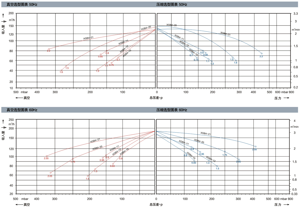
The following performance curve is measured under the condition of suction of 15 ℃ air and exhaust pressure of 1013mbar. When the tolerance is & plusmn; 10%, and the suction air and ambient temperature are not more than 25 ℃, the total pressure gauge shown in the figure can be reached.